Tabletop Simulator

Tabletop Simulator

62 ratings
Step by Step Tutorial on Basic Object Modeling
By Party Hat
This guide is a step by step tutorial on making a 3D object for use in Tabletop Simulator. It Uses Blender as the modeling software and MS Paint for making the texture (though I recommend using a program like Paint .net). I walk through step by step assuming no knowledge of Blender modeling and with 43 pictures!

This is a good starting point if you want to make custom content and have no experience modeling in Blender.

Another plus to this guide is that all the software I use is free so there is no cost barrier.

I learned modeling in Solidworks first and taught myself how to model for tabletop in Blender about a week ago. They are certainly different and I couldn't find a good guide on how to do it specific to Tabletop so I had to work though numerous guides and put all the pieces together. This guide is the guide I wish I had when I was trying to learn.
2
   
Award
Favorite
Favorited
Unfavorite
Introduction
The first step to making models in Blender for Tabletop Simulator is downloading Blender. The latest version can be found at https://www.blender.org/download/.

In this Tutorial I am using version 2.78 which is was released on February 24th, 2017. Newer versions should work as well as older ones, since we are not doing anything crazy here.

I also use MS Paint durring this tutorial but I would reccomend a more powerful alternative for anything that is more complicated than a few poorly placed stripes and circles (you'll see what I mean). Paint .net is a great free alternative that allows for more precise textures as well as supports layers and transparency to help create things more interesting. Paint .net can be found at https://www.getpaint.net/download.html

This tutorial is certainly not about advanced modeling or making complex RPG Figurines but it should be all you need to get started making symmetrical tokens similar to chess pieces for your games. If the demand is there I may make one for pieces that are more than just a bunch of circles, let me know in the comments.

So let's go!

Quick Note on controls:
Ctrl Z is your friend
A is deselect all, and select all if there is nothing selected
Number Pad can help with camera an, 1, 3, 7, and 9 are specific and 2, 4, 6, 8 are arrows to move the camera. Or you can Middle Mouse Button and rotate that way.
Modeling

Step 1 Open Blender! it will open up to this default scene with a cube, a camera, and a light. We don't need to care about the camera and the light, only the object that we create. So let's start by deleting this Cube. Right Click on the cube and press the delete key on your keyboard.

Side note: Some tutorials I found say switch from Blender Render to Cycles Render. That maters if you are looking at the scene rendering in Blender, not at all for Tabletop Simulator

So no more cube. If you left click somewhere the cursor will move around in the 3D space. For our next step we want the cursor to be at the origin point. On your keyboard Shift + S will open a menu that has some cursor options. Click Cursor to Center to recenter the Cursor


With the cursor in the center go to Add -> Mesh - > Cylinder to put a cylinder where the cursor is. This is our starting point. After the Cylinder appears press F6 to open more options for the primative (in this cast our Cylinder). Here two things matter, Number of Vertices and Cap Fill Type.
  • The number of vertices determines how much resolution your part will have. The lower the number the more blocky your object will look, higher then the harder it is to work with and the larger the file which may affect the performance in Tabletop Simulator. I made this Cylinder 64.
  • The Cap Fill Type determines how the face on the top and bottom of the cylinder will be created. The default is ngon (n sided polygon) but this does not work with Tabletop Simulator. I am not sure what the limit to n is for Tabletop Simulator but I know it can do 3 sided and 4 sided polygons. So let's make it a triangle fan.


Now let's go into Edit Mode and set our view mode to Wire frame. This makes seeing our model easier. These options are boxed in red bellow:


Blender uses the number pad to adjust the camera angles. If you're on a laptop and don't have a number pad the view menu has the same options. I pressed 1 on the Numpad to align to Front View and 5 on the Numpad to switch from Perspective to Orthogonal mode. This gives a nice grid behind the model to work with.


Now we are going to delete everything except the base of our model. Pressing B on the keyboard starts box selection. Left click to draw a box around the top points. The selected points will turn yellow.


Pressing Delete on the keyboard and then click vertices. This will leave just the base.

You can adjust your view using the number pad or by clicking down the middle mouse button. The Number pad 2, 4, 6, and 8 serve as arrow keys to rotate the view. Using the mouse wheel you can zoom in and out, Shift mouse wheel will pan up and down, and Ctrl mouse wheel will pan left and right.


Right Click is select one by one. We want to select the entire outer circle. The easiest way to do that is to switch to edge selection and Alt Right Click one edge on the circle. The Alt modifier is used to select all edges in a continuous path, in our case the outside of the circle.


We are now going to start making the shape. With this circle selected press E to extrude the circle. Press Z to constrain the extrusion to the Z axis. This will make sure the circles are of the same size and concentric on that axis. Move the mouse up and click to finish the extrusion.

Note: you can see the axis triad in the bottom left of the view window if you are unsure of your orientation


We can now move the selected circle with the triad in the middle of it if we want it to be taller or shorter. However moving it in X and Y will make our circles out of line.


When making a part that is symmetrical like this there are essentially two things you mess with, height of circle and radius of circle. Move the height by using the proper arrow on the triad (in this case Z which is blue (Also Z is up in tabletop too)). If your specific you can type in stuff in the box on the left but I usually eyeball it.

I find the best way to change the radius is to use the scale tool. If all the selected vertices/edges are in the same plane then it will keep them in that plane and only adjust the radius. Do this by pressing S on the keyboard and then either typing in a ratio (like .9) and pressing Enter or by using the mouse (depends on how precise you are trying to be).
See how this is angled in now?


Say you want to make a step that doesn’t go up at all, only in or out. First extrude (E)the circle again (pressing Z so it is in the Z axis only and is lined up) and go up a bit just so it is easy to see what we are doing. Again if you want more space you can move the circle up and down with the triad (blue arrow, Z axis)


Press S to scale it in as much as you want your step to be. Now you can eyeball it with the triad to make it level if you want but I am particular about it so I like to get them into the exact same XY Plane.


Alt Right Click to select one circle then Shift Alt Right click the other one (Still in edge mode!) so the two circles are highlighted.


Press S to scale, Z to constrict the scaling to the Z Axis (Up and down so they get closer and further vertically as you move the mouse) and then type 0 and hit Enter. This scales their distance in Z to zero -> puts them on the same XY Plane. You can now move the Step as a whole with the Triad, or scale the inner and outer circle independently like before, just Alt Right Click the circle you want and then press S for scale and move the mouse (or type a decimal depending on your preference).


I am going to continue modeling over the next few pictures. I am only using extrude in Z, translate in Z (with the triad) and scale one circle at a time. More instructions on finishing the model below.

I first extruded in Z a few times so I can see the whole curve as I make it. More extrudes -> more resolution of the curve and less blocky in Tabletop Simulator.


Also Box select (B) works as well as Alt Right Click if that’s easier for you in a particular view. This is Front View (Numpad 1).


So how do we finish? So far everything we have made (after deleting the top and sides of the cylinder) has been a cup, a bottom and sides but no top, how do we close it off?

Here is the top opening of the model. We could just make the hole smaller by scaling it to 0 and moving on having all the vertices be coincident. But that’s sloppy and because this is gaming sloppiness turns into ram consumption. Not a big deal on one little token but it can add up. There two ways that I use to close off models, one for flat top parts and one for pointy parts.


Finishing The Model: Two Methods
Flat Top Method:
Alt Right Click the top circle to select all those edges (Still in edge mode!) then hit F on your keyboard. This will make an ngon face between all the selected edges.


But if you remember from the beginning, Tabletop doesn’t like ngons so it just ignores them, we need to make this a bunch of triangles to make up this ngon. Switch to face selection mode, find the dot in the middle of the face and Right Click on it. Then in Mesh -> Faces choose Triangulate Faces.


Finished Product:


Model Goes to a Point Method:
This is what I am using because this is what our model does. First extrude the top circle in Z one more time. Make it tall enough that it is easy to box select it while in your preferred view.

Then switch to vertices mode and select all the vertices using box selection (B)


Now merge all of these vertices into one. Mesh -> Verticies -> Merrge. There are options but I chose at center so that the point is in line with the center axis of our model.


Move it up and down using the triad and boom, you’re done with your model!


Move it up and down using the triad and boom, you’re done with your model!
UV Textures
Now we have a model but no texture. This is how I do texturing.

Note: If your piece is just one solid color then you don’t have to do this, you can just color it in Tabletop Simulator!

Go into Object Mode and set view mode to Solid and have a look at your 3D model, now is when you should make any changes to make it look right.
Once you’re satisfied with it we need to make sure that its Center Of Mass (Approximately of course) is on the origin point in Blender. This is where the Tabletop Simulator physics acts so it would be weird if it was at the top point or not even in the model.


You can move it around with the triad or select Object on the left and type in Cartesian coordinates. Making it 0,0,0 is usually good but in this case it is a little low. I am sure blender does some math to find the center of the model based on faces or vertices or something but I am not sure as to the specifics, just eyeball it.


Switch your window layout from Default to UV Editing. Switch back to edit mode and wire frame.


Go ahead and select all and then go to Mesh -> UV Unwrap and click Smart UV Unwrap. Click ok because the default settings are pretty good. Your left side should now have this mess of things on it.


Aside about UV Seams: If the UV from the smart unwrap still just gave you something that is not easy to see where the sides are or it was cut in weird places you can set up UV Seams. In the right side click the edges of your model where you want a UV cut to be and insert a seam. This will make the smart UV tool make the cuts there and can leave you with a more intuitive UV map.

So this is a mess, how do I know what face goes to what? The left side of the screen only outlines selected parts of the right side of the screen. So if I Switch to face select mode and box select (B) the faces at the top it will show us what circle on the left corresponds to the textures on the top. If we do this enough we can get a feel (or take notes) of where each face is on the map.


Once we think we know where everything is we need to export this lay out. Select everything (A to deselect, A to select all) and click Uvs -> Export UV Layout and save it somewhere.


Personally I use Paint .net to do my UVs but I am going to use MS Paint for this tutorial to just keep it simple. Open the exported image in the editor of your choice. I am going to do a striped pattern to easily convey what is happening. Remember if you are not sure where a face is you can go into Blender and select it and see where it is highlighted on the UV view.


A beautiful work of art. Its hard to tell but there should be two stripes across the mid section, the top should be red and the bottom should have those two circles, back to blender to see it work.


At the bottom Click Open Image and select your masterpiece. As you can see here my paint skills are lacking. The circles aren’t concentric, the top stripe cuts through the other faces that are not on the side. Essentially I goofed. But this is only a tutorial.


To see it in Blender change your view mode to Texture. I also recommend switching to edge mode to get rid of all the face dots. Looks good (ish) so lets put it into Tabletop Simulator!


And now it is ready for Tabletop Simulator complete with textures!
Importing Into Tabletop Simulator
First we need to export our model into something Tabletop Simulator can use, a .obj file. File -> Export -> Wavefront (.obj).


Boot up Tabletop Simulator!

In a single player game go to Objects -> Components, and click Custom.


Click Model


Up comes a dialog, this is how we get our stuff into Tabletop Simulator.


Those files we saved? The OBJ goes to the Model/Mesh, as well as the Collider. The UV image goes in Diffuse/Image. It will ask if you want cloud or local. I recommend doing local for now and then after you confirm everything is working do it again with cloud. The cloud allows you to use these objects in multiplayer and mods, local is just you. Chose the appropriate Type and Material Settings and click import!


Here it is, with all of its beautiful texturing.


Remember you can scale things in Tabletop Simulator to make them the appropriate size for your game.

I hope this guide was helpful, Happy Modeling!

6 Comments
TimeDivided 13 Oct, 2020 @ 9:57pm 
Im getting hit or miss success on this. Im painting Miniatures in blender. I pull in the obj, unwrap it, texture paint it, paint the mesh, save as png. When I go back to TTS, sometimes I can apply the mesh correctly, other times the a single solid color from the pallette is applied to the object. Any Ideas why? The obj files were exported from TTS in the first place, so I dont imagine its a problem with the models; I know they work in TTS. Any help decrypting this would be greatly appreciated.
Party Hat  [author] 5 May, 2020 @ 8:25pm 
@Silver Mountain

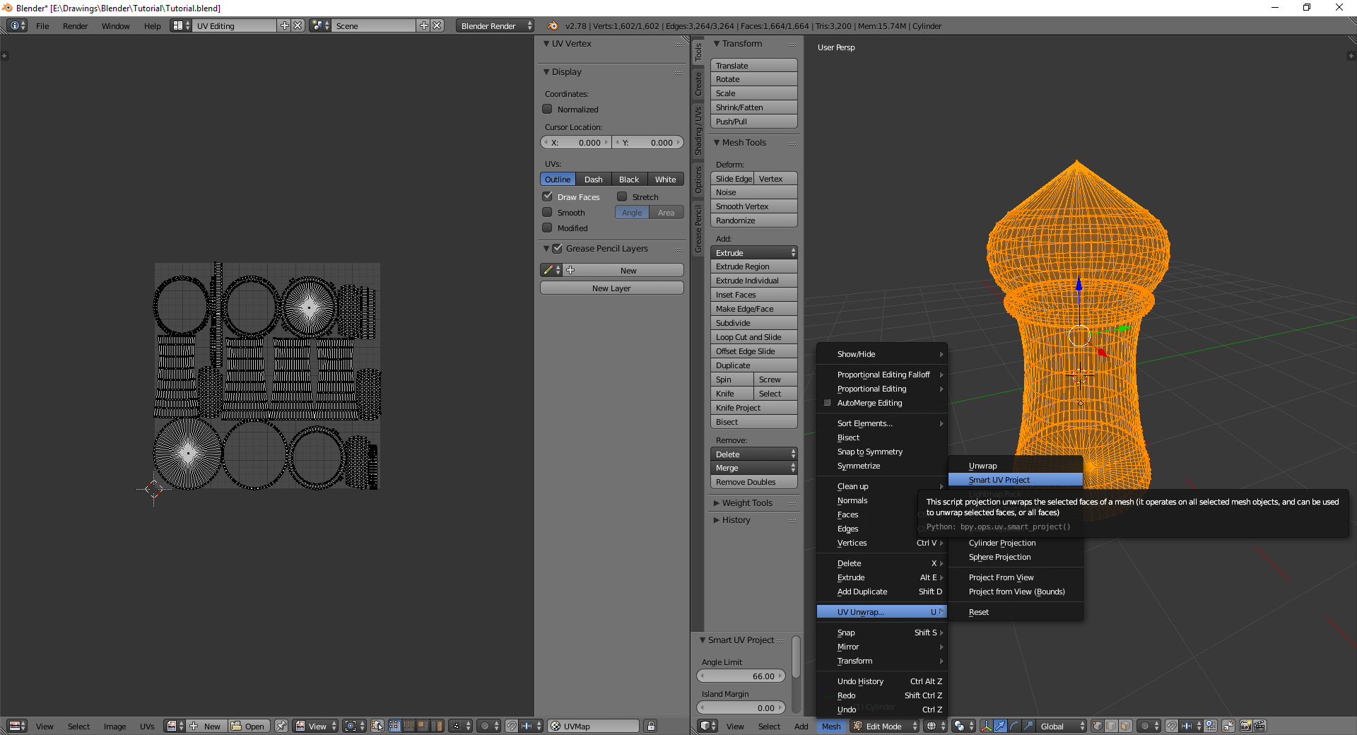
I haven't played with it in awhile but make sure your model is solid. I think if a face is deleted or some edges make a hole then tts can't import it
LANCER 28 Apr, 2020 @ 4:17pm 
I have a model I already want to use, an .stl file. I imported it into Blender then exported it as an .obj file. After trying to put it into Tabletop Sim using your instructions (.obj into both Model/Mesh and Collider fields), I get the error "Failed to load Model (.obj): file directory ". Can you help with this?
Kagekaze 10 Jun, 2017 @ 1:03pm 
I just checked a board from a mod that uses a 4096 squared texture, so it can certainly go higher, I guess the question at this point becomes how to get Blender to use a higher texture resolution, or... can the texture just be resized to fit. I can't test right now, so was hoping you'd know. :)
Party Hat  [author] 5 Jun, 2017 @ 9:06am 
@Kagekaze

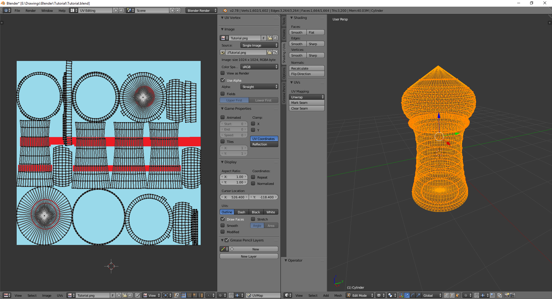
Unfortunately I think the 1024x1024 is the set texture size for everything in TTS, but I cannot find that anywhere official so I am not sure if there is a work around. If you find one please let me know!
Kagekaze 2 Jun, 2017 @ 9:01am 
Thanks for putting this together, it's helped me much more than a lot of the stuff I've found on my own. I'm trying to make a simple board (cube) and i realized that the UV map saved as a 1024x1024 which is about 1/3 of the size of the image I plan to use as a texture. I tried scaling the cube to double the size, but the UV map appeared to be the same.. can I simply double the size of the texture and will TTS know what to do with it if I do?