
Install Steam
login
|
language
简体中文 (Simplified Chinese)
繁體中文 (Traditional Chinese)
日本語 (Japanese)
한국어 (Korean)
ไทย (Thai)
Български (Bulgarian)
Čeština (Czech)
Dansk (Danish)
Deutsch (German)
Español - España (Spanish - Spain)
Español - Latinoamérica (Spanish - Latin America)
Ελληνικά (Greek)
Français (French)
Italiano (Italian)
Bahasa Indonesia (Indonesian)
Magyar (Hungarian)
Nederlands (Dutch)
Norsk (Norwegian)
Polski (Polish)
Português (Portuguese - Portugal)
Português - Brasil (Portuguese - Brazil)
Română (Romanian)
Русский (Russian)
Suomi (Finnish)
Svenska (Swedish)
Türkçe (Turkish)
Tiếng Việt (Vietnamese)
Українська (Ukrainian)
Report a translation problem


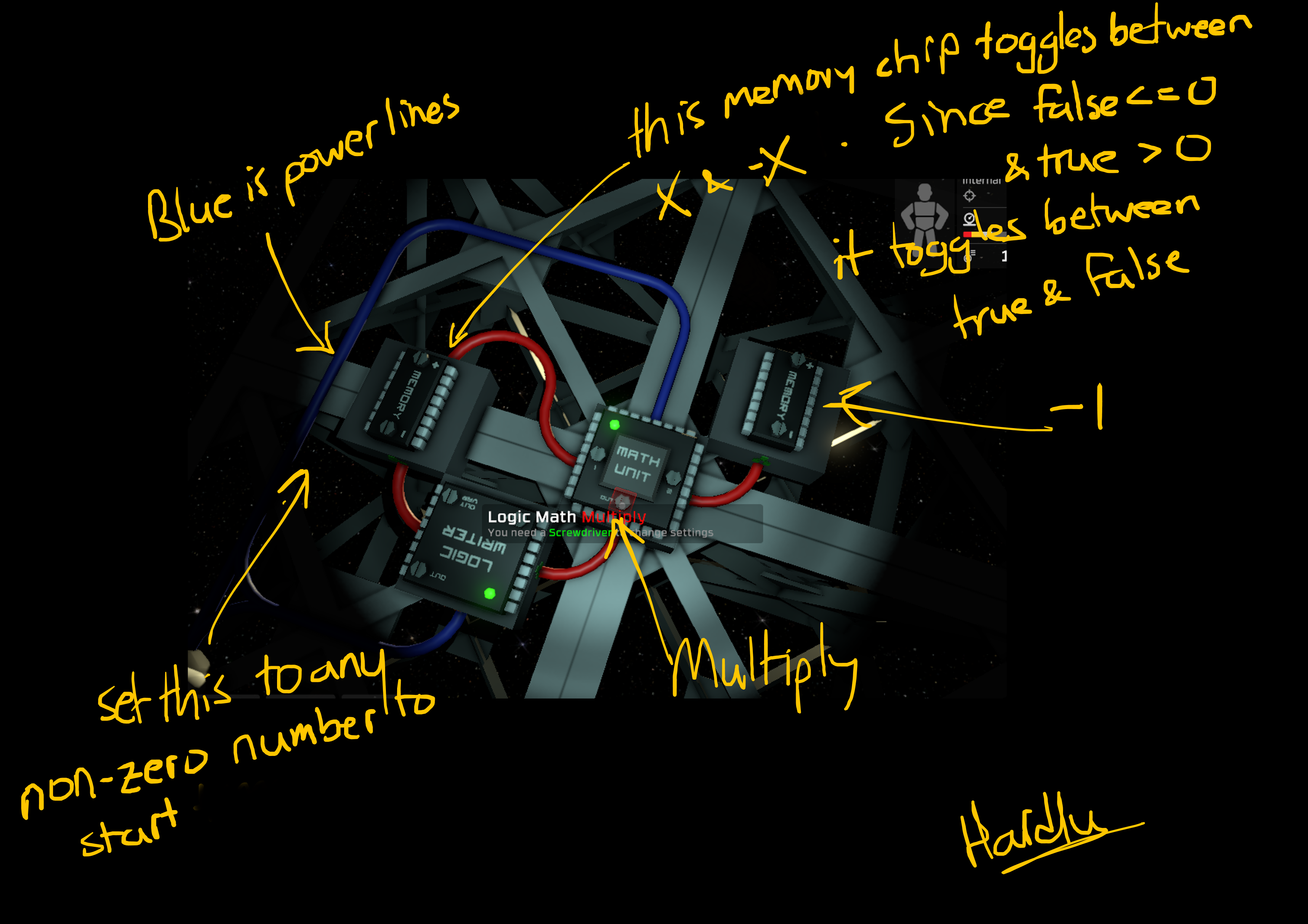


dlatch(x,s) =
y = if s then x else max(y,y)
single circuit version:
y = if s then x else y
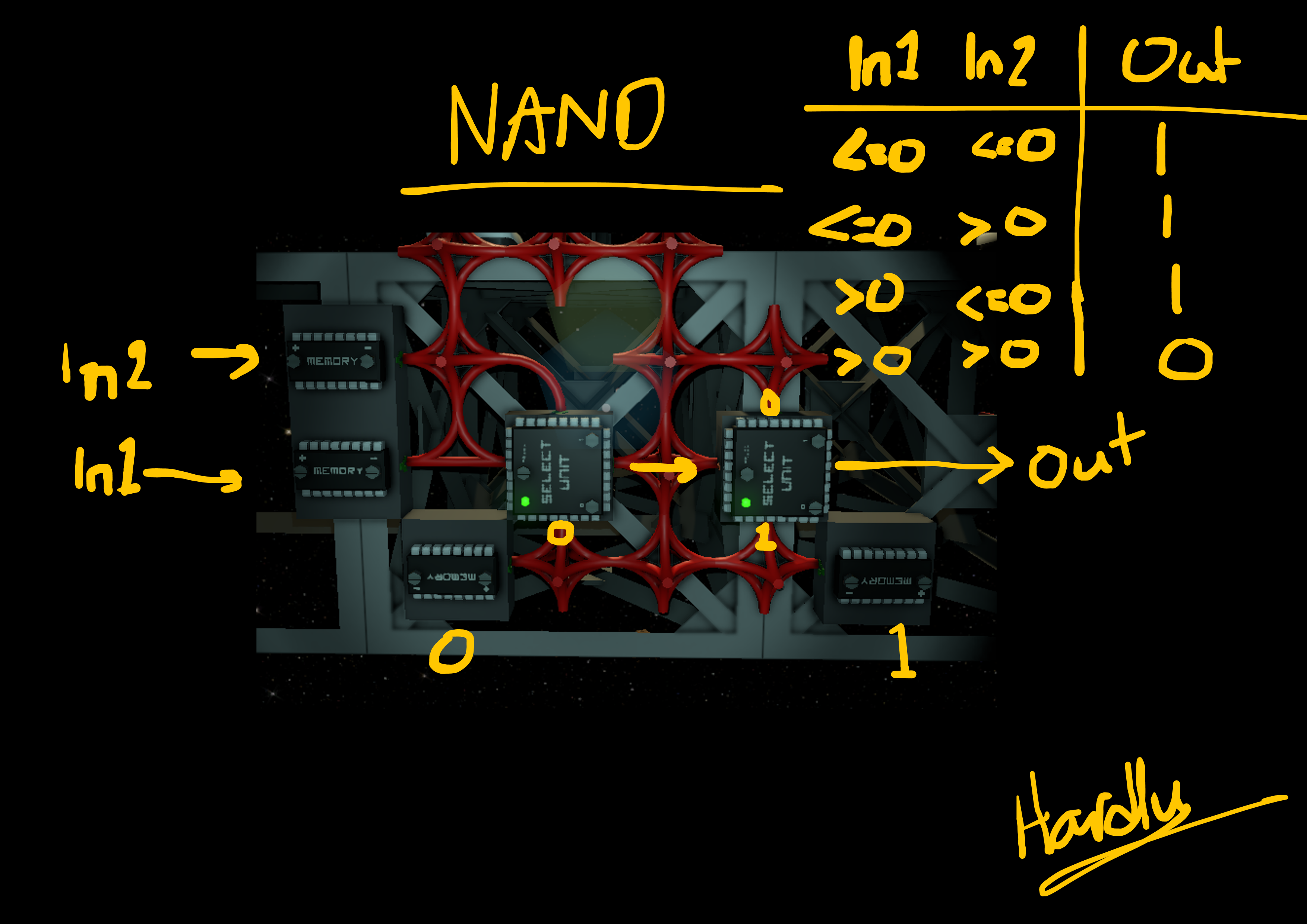
AND : A * B ( MIN(A,B) works also )
OR : MAX(A,B)
XOR : A != B ( != means "not equal" )
NOT : 1 - A (this one uses an additional memory chip to store 1)
Just one improvement about the AND gate.
Test (a+b) == 2
While this is certainly correct, it needs a math processor to add a and b, followed by a compare processor, to compare(equals) the sum with a "2" from memory.
It can also be done with just one math processor set to multiply.
0*0=0
0*1=0
1*0=0
1*1=1
Compare(equals) the result to "0" from memory, to make it a NAND gate.
An "equals 0" compare operation would also work, which is probably a more intuitive solution.
I've been thinking all day about writing article like that)
Just went to the manuals page to see if its written by someone...
And thats it)